Sequence diagram - one of the available kinds of graphs supported Flexberry Designer.
Sequence diagrams are used to clarify the diagram precedents, a more detailed description of the logic of usage scenarios. This is an excellent tool for documenting project terms of usage scenarios!
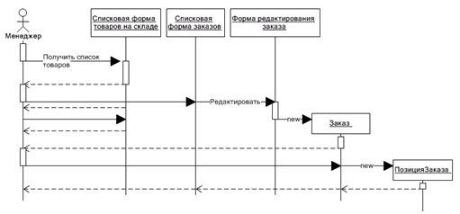
Sequence diagrams commonly contain objects that interact within the scenario, message they exchange, and return results related messages. However, often the results returned indicate that only if it’s not obvious from the context.
Objects are denoted by rectangles with underlined names (to distinguish them from classes).
Messages (method calls) lines with arrows.
Return results - dotted lines with arrows.
The rectangles on the vertical lines under each object show “lifetime” (focus) objects. However, quite often they are not portrayed in the diagram, it all depends on the individual style of designing.
The basic elements of sequence diagrams
On the sequence diagram, you can display the following elements of UML notation that are available in the Toolbox:
| Element/Notation | Purpose |
|---|---|
 |
Participant (Actor) |
 |
Object (Object) |
 |
the Active object (Active object) |
 |
the Terminator (Terminator) |
 |
procedure Call (Procedure call) |
 |
Message (Flat message) |
 |
Asynchronous message (Async message) |
 |
message with the result (Return message) |
 |
time interval (In scope) |
 |
temporal limit (Time constraint) |
 |
Point of bending of the links (Point) |
 |
Comment (Note) |
 |
Connector review (Note the connector) |