Deployment diagram - one of the available kinds of graphs supported Flexberry Designer. Enterprise applications often require for its operation a certain it infrastructure, store information in databases located somewhere on the company servers, cause the web services, share resources, etc. In such cases, it is useful to have a graphical representation of the infrastructure on which the application will be deployed. What is needed, and deployment diagram, which is sometimes referred to charts placement.
Such diagrams make sense to build only for hardware and software systems, whereas UML allows to build models of any system, not necessarily computer.
Use a deployment diagram
- A graphical representation of an it infrastructure can help to more efficiently distribute system components on the nodes of the network, which determines including the performance of the system.
- Such a diagram could help to solve numerous tasks associated with, for example, security.
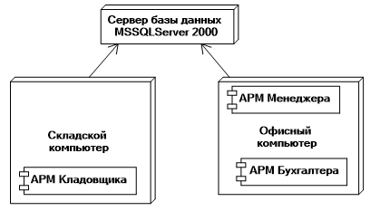
The deployment diagram shows the system topology and distribution of components of the system in its nodes and connections - routes of information transfer between the hardware nodes. This is the only chart that used a “three-dimensional” notation: nodes of the system are denoted by cubes. All the rest of the notation in the UML a plane figure.
The main elements of deployment diagram
In the diagram the deployment you can display the following elements of UML notation that are available in the Toolbox:
| Element/Notation | Purpose |
|---|---|
 |
Component (Component) |
 |
the component Instance (Component instance) |
 |
Interface (Interface) |
 |
Node (Node) |
 |
host Instance (Node instance) |
 |
Object (Object) |
 |
the Active object (Active object) |
 |
Addiction (Dependency) |
 |
Communication (Connection) |
 |
Point of bending of the links (Point) |
 |
Comment (Note) |
 |
Connector review (Note the connector) |